Jewelbots WearablesKit
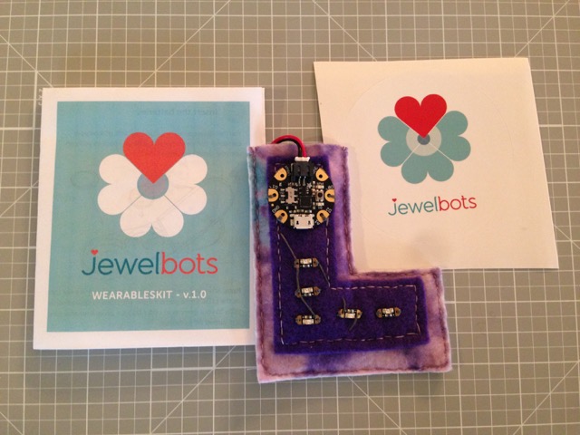
We recently purchased the Jewelbots Wearables Kit 1.0 and built this lovely felt “L” that is soon getting attached to a backpack.
I have been a software engineer for twenty years, but never did much with hardware and electronics. The Jewelbots kit is a good entry to this world.
In the kit
The Jewelbots WearablesKit contains:
- An Arduino Gemma
- Five Adafruit LED sequins
- Conductive thread
- Battery holder
- Two cell batteries
- Sewing needles
Jewelbots uses Adafruit parts to build their kit, which retails for $29 and comes in a branded box, stickers and a small instruction booklet. Adafruit offers the same kit for about $20.
I wish that the Jewelbots kit had a few more pointers to code or examples of code that would be appropriate for the kit. Their wearables website is empty right now. I eventually found a bunch of help on the Adafruit site - their sequin hat was a great help.
These critiques are pretty minor, though. I really admire what both Jewelbots and Adafruit are doing to make it really easy for my family to get started with this type of project.
Getting Started
I’m not going to talk about the Arduino IDE or getting the IDE propertly configured for the Arduino Gemma. I did have some difficulty getting started; the first USB cable I tried happened to be a power-only cable that originally came with one of our phones. That cable mix-up caused me to flail a little when setting up the IDE - it took me a while to rule out other things before swapping out the cable.
There is lots of help out there to help you get going with an Arduino Gemma and the Arduino IDE. Start with the Adafruit instructions and go from there.
Alligator clips
I found that it was really helpful to play with wiring and layout before sewing everything together. I picked up a set of small alligator clips from Adafruit. They let me mess around with different groupings of lights in a very non-permanent way. You could probably accomplish the same thing with bits of wire.
Fabric
We used three layers of felt to build a letter “L” design. The bottom layer is a thicker, stiff felt that prevents the project from flopping all over the place. The top piece of felt was cut just wide enough for the Gemma to fit on top. We are going to be using the light on the Gemma in our design and did not want to hide it.
The top two layers were sewn together and then the Gemma and LEDs were sewn on top. After the circuit was sewn and tested, we sewed the stiffer felt to the bottom of the joined layers. The top seam of the “L” was left unstitched and is the perfect pocket for our battery pack.
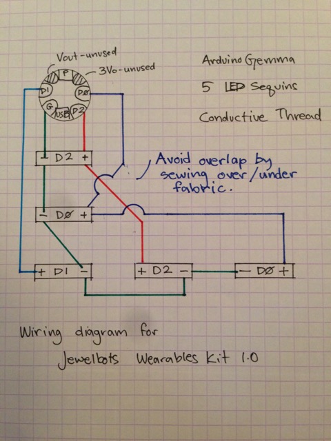
Wiring
Two LEDs are wired to D0. Two are wired to D2. The final LED is wired to
D1. The Gemma has a D1 light in the center of the board, meaning we also
have two D1 lights!
When laying out the Gemma and LEDs, you can get a nice pattern by creating a
chain. In the following illustration, I have annotated the Gemma and LEDs by
the data line connecting to the light. Remember that the Gemma has a D1
light at its center.
Gemma(D1) - LED(D2) - LED(D0) - LED(D1) - LED(D2) - LED(D0)
If you just try and lay out this design on a flat surface, you are going to have a hard time avoiding overlapping wires. This might not matter when using coated wires, but it makes a different when sewing with conductive thread!
Avoid letting those overlapping threads touch by separating the thread with layers of fabric. Thick fabric like felt worked well; thinner fabrics might not be as effective. In two spots, I used some normal thread to tie pieces of conductive thread in place, preventing them from shifting over time.
Code
Here is the code that we currently are running on our project. We aren’t done experimenting, but I wanted to post this very simple design for others who might want to follow our example.
We aren’t using the power of
analogWrite yet. We are
turning the D0 and D1 pins on and off; no partial luminosity. The D2 pin
doesn’t support analogWrite, meaning we have to use
digitalWrite instead.
The Adafruit Gemma guide has more information about what each pin supports.
This code is only slightly changed from Adafruit’s sequin hat project.
uint8_t b0,b1 = 0;    // how bright the LED is
uint8_t d2 = HIGH;
uint8_t counter = 0;

void setup()  {
  // declare pins to be an outputs:
  pinMode(0, OUTPUT);
  pinMode(1, OUTPUT);
  pinMode(2, OUTPUT);
}

void loop()  {
  if (counter % 30 == 0) {
    b0 = ~b0;
    analogWrite(0, b0);
  }

  if (counter % 50 == 0) {
    b1 = ~b1;
    analogWrite(1, b1);
  }

  if (counter % 70 == 0) {
    d2 = (d2==HIGH) ? LOW : HIGH;
    digitalWrite(2, d2);
  }

  delay(10);
  counter++;
}
And now, for a little blinking.